
±9 arcsec across the full ±0.5 mm of axial tolerance. No shims. No gap gauges. No inspection jig. No calibration run after mounting.
Fit the target, bolt the stator, plug the cable. The encoder calibrates itself during the first partial turn, then holds full datasheet accuracy at standstill and on every power-up.
Measured position error
Internal position update
Air gap installation margin
Correction even at standstill
Our metal-target sensor IP is licensed to Balluff, Continental and TT Electronics and ships inside their automotive and industrial linear sensor ranges.
For our Kit Encoders, we chose resonant-target technology to deliver much better accuracy and wider installation margins.
That choice turns a complex installation procedure into a simple screw-and-forget production step. No precision shimming. No air-gap inspection. Fit the target, bolt the stator, plug the cable. Screw-and-forget.
The encoder invoice does not include the shim stack, gap gauge, inspection jig or calibration fixture.
Somebody has to write the work instruction for setting the tight air gap. Somebody has to follow it, on every unit, for the life of the product. Somebody has to own the inspection step, keep the fixture qualified, train the operators, retrain them, and take the call when a unit that passed the bench comes back from a customer.
None of that is on the encoder invoice. All of it is on your line. CamEncoders Kit Encoders remove that work.
CamEncoders Kit Encoders allow a nominal air gap of 1.4 mm ±0.5 mm and need no post-installation calibration run.
Inductive encoders measure coupling around the full circumference, so rotor eccentricity averages out. Concentricity stops being an accuracy problem. It becomes a ±0.15 mm radial alignment tolerance. Inductive sensing also stands up to dust, oil, condensation, shock and vibration.
But inductive kit encoders are not yet screw-and-forget. The axial gap is still tight, with a typical nominal air gap around 0.35 mm and permitted variation typically ±0.125 mm, so shimming, inspection, and sometimes a calibration run remain part of assembly.
We eliminate the installation burden. Four times the air gap. Four times the tolerance margin.
Every CamEncoders Kit Encoder assembled anywhere in the ±0.5 mm window meets specification after its first partial turn. Fewer rejects. No rework.
Before you commit to precision gap setting on every build, discuss your installation with us.
Has a batch of machined parts ever held up a build because the encoder’s air gap became out of tolerance?
An axial tolerance window is a budget. Housing stack-up, bearing end-float and deflection under load all spend it. At ±0.1 mm, the assembly stack alone consumes more than the window allows, and what remains after shimming must cover everything else.
At ±0.5 mm, the assembly stack takes a fraction, and the rest is margin. That is the difference between a tolerance you manage at every build and one you stop thinking about.
A tight air gap is not an oversight waiting to be resolved in your supplier’s next product generation. It is a fundamental choice driven by sound engineering.
More fine-scale periods improve datasheet position accuracy and shorten the rotation span needed for self-calibration. However, more periods mean a shorter spatial period, with a proportionally smaller nominal air gap and tighter installation tolerances.
Our wider air-gap tolerance comes from lower error within each fine-scale period. That lets us use fewer periods without sacrificing datasheet accuracy.
Inductive encoders correct their electrical zero while the rotor turns. On a shaft that keeps turning, a modern encoder keeps that correction fresh and holds its published accuracy. That is sound engineering, and it is the right answer for a motor shaft.
The limitation appears when an axis holds position or works within a small arc for prolonged periods: a direct drive under load, a tracking gimbal, or a robot arm whose workpiece is brought to it.
On those axes, the correction that depends on rotation has nothing to work with, so the drift accumulates as the motor warms. The controller follows the encoder’s drifting zero.
A temperature test that turns the shaft will not show it. Months later, the customer calls. Their machine has a fault nobody can reproduce.
CamEncoders Kit Encoders correct the analogue receive chain at a 400 Hz update rate even if the shaft stands still. Full ±9 arcsec at power-up, at zero speed, and after a dwell of any length, from −40 °C to +115 °C.
Gap setting, inspection and calibration are paid for on every unit, for the life of the product, and none of it appears on the encoder invoice.
A temperature test that turns the shaft will not show drift that only appears when the axis holds position.
The datasheet accuracy figure does not describe the error in derived motion such as calculated velocity and acceleration.
Find out why we use resonant-target technology when most manufacturers use a metal-target approach. See why inductive sensing relaxes radial alignment, why the axial air gap usually remains restrictive, and how our receive-chain self-calibration continues without rotation.
Use the information we provide in your design review. Ask production and purchasing to compare the cost of achieving datasheet accuracy on every unit. Our designers can join the call and answer your team’s questions directly.
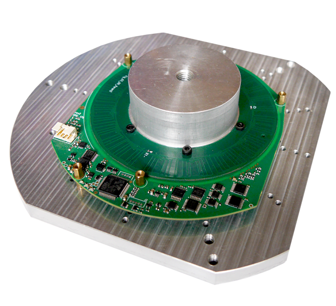
Tell us the outer diameter you can fit, the clear bore you need, and how far the axis travels in normal operation.
Nine standard sizes, with outer diameters from 70 to 200 mm and clear bores from 20 to 110 mm. Patented architecture. Designed in Cambridge.