Modern inductive encoders run motion-gated self-calibration continuously. They meet their datasheet specifications while the shaft is turning. Axes that hold position do not receive updated corrections. Calibration parameters become stale, and position accuracy degrades.
CamEncoders develops patented resonant-target inductive Kit Encoders. Full accuracy at power-up, at standstill, and after any dwell. Receive-chain self-calibration continues at 400 Hz even without rotation, maintaining standstill accuracy as temperature changes.
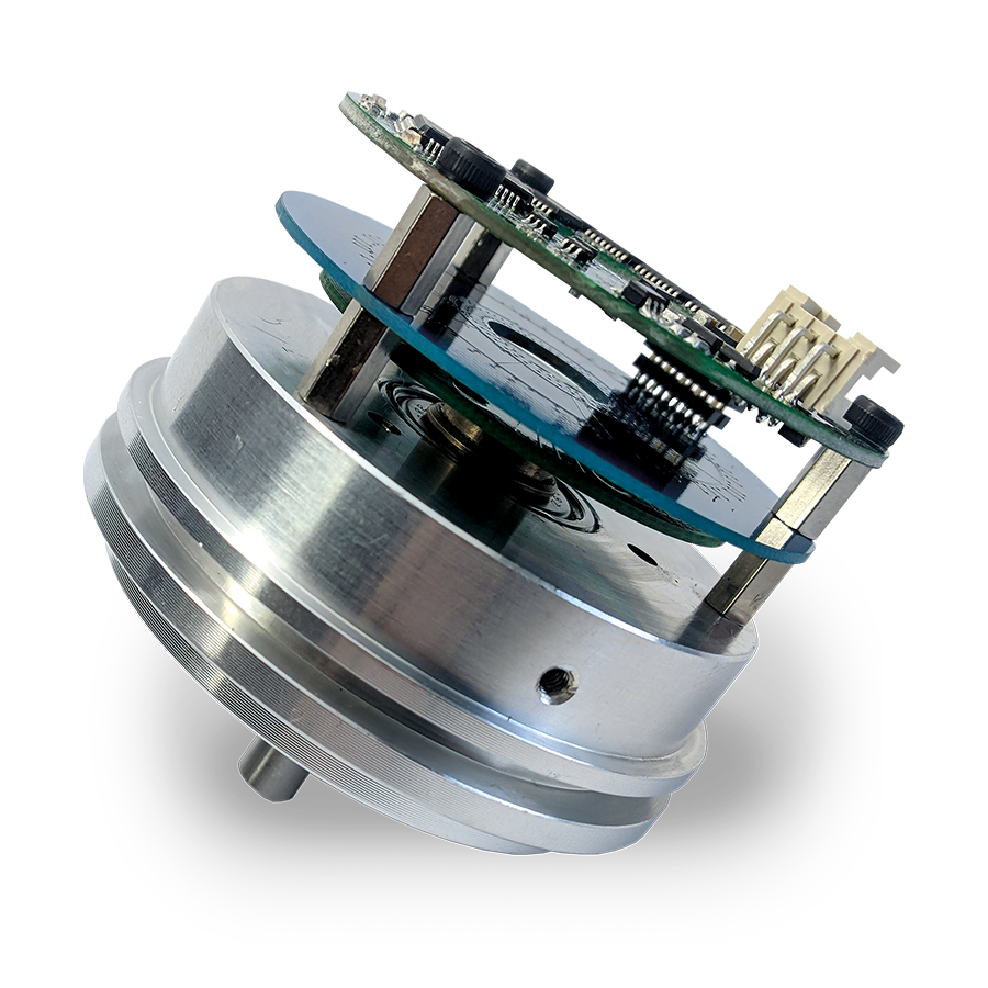
An optical or magnetic encoder reads its scale in one spot. No disc is ever perfectly concentric with the axis of rotation, and the radial displacement of the scale under the read-head becomes a position error.
The cost is published. Heidenhain’s Renco R35i optical encoder brochure states that for one micron of measured shaft eccentricity, the measuring error increases by ±16.4 arcsec. Thirty microns, an otherwise unremarkable tolerance, is roughly ±500 arcsec of position error.
This is why precision optical and magnetic installations need fixtures, inspection and often a calibration run. The encoder disk specification looks excellent. Achieving datasheet accuracy is your problem. Your assembly process has to deliver.
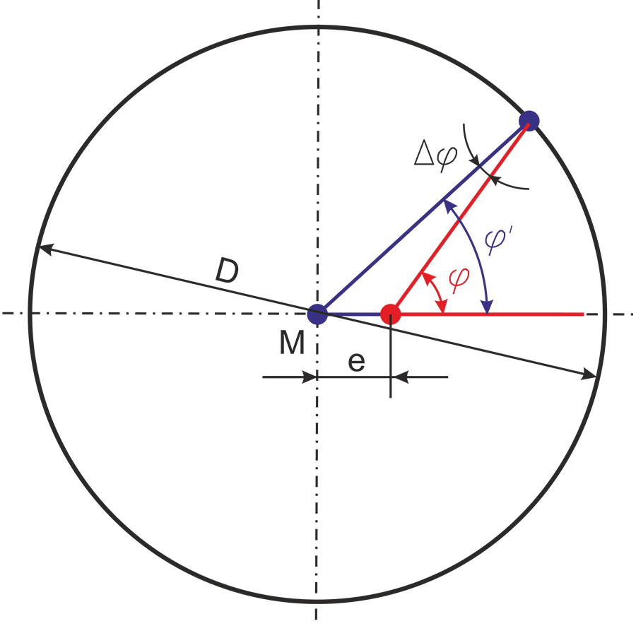
Figure 1 — geometric error. A sinusoidal error Δϕ caused by eccentricity e in an optical measurement. M = centre of graduation; ϕ = true angle; ϕ’ = sampled angle.
An inductive encoder does not read at a point. The stator windings couple to the target around the entire circumference, so the measurement averages over the whole perimeter rather than sampling at one angular position.
Shift the rotor toward one side of the inductive sensor stator, and coupling increases on that side while it decreases on the opposite side. To first order, the two cancel. It is a simple consequence of the rotational symmetry of the sensor and the target.
Concentricity stops being an accuracy problem and becomes a tolerance. Inductive encoders tolerate ±0.1 to ±0.2 mm of radial misalignment, while optical and magnetic devices demand a few microns. That factor of almost a hundred is why many customers move to inductive sensing, and every inductive supplier can offer that benefit.
An inductive encoder does not measure angle directly. It measures a sine-cosine pair that repeats N times per revolution. Each repetition of that pattern is a fine-scale period. Within one period, the encoder electronics compute electrical angle as the arctangent of the ratio of the two received sinusoidal signals; a coarse track identifies which period the rotor is in.
Electrical zero shift is the hardest issue in inductive sensors: voltage offsets in the sine and cosine receive channels produce periodic angle non-linearity. Correcting those offsets still leaves higher-harmonic errors caused by departures from sinusoidal shape in receive signals. These set the remaining non-linearity floor.
Fine-scale period count N is the central design decision, and almost everything else follows from it. Shaft-referred, or mechanical, position error is the electrical position error within one fine-scale period divided by N. Raise N, and the position error recorded on the datasheet improves as 1/N. The whole industry has taken that route, and for good reason.

Figure 2 — electrical error. A sinusoidal error Δϕ due to breakthrough in the measurement of Vsin and Vcos. The shift of the received signals from zero resembles eccentricity, but it is a completely different problem.
A multi-period measurement system retains similar non-linearity within each fine-scale period. The error repeats N times per revolution, with higher harmonics at multiples of N. The 360° eccentricity-error period gives way to fine-scale error periods of 360°/N and shorter.
A faster error is not a smaller error. Where a control system derives velocity from successive position measurements, the 1/N that improves the datasheet figure is cancelled by the N-times boost that differentiation introduces. Velocity error is set by the electrical accuracy within one fine-scale period and by nothing else. Differentiate a second time to obtain acceleration and the period count no longer cancels. There, a high period count is a penalty.
Applications that predict position beyond the latest measurement make this distinction critical. Prediction amplifies high-frequency error content, producing large errors in the predicted point. Conventional encoders with higher N deliver worse predicted performance. The lower N of our Kit Encoders shifts position error to lower frequencies, reducing prediction error.
If your application predicts beyond the latest measurement, talk to us about the trade-offs.
A high N count improves published position accuracy, reduces the angular travel needed for self-calibration, and moves periodic error beyond motor controller bandwidth even at low shaft speed. For position error frequencies above motor controller bandwidth, torque-loop filtering reduces the remaining angle error at the shaft output as 1/N. For conventional motor control, high N is the right choice, and the industry chose it for good reasons.
Those benefits come at the cost of a shorter spatial period for large N-count encoders, which translates directly into a smaller sensing gap and tighter installation tolerances.
Our proprietary sensor design reduces electrical error within each fine-scale period roughly tenfold. That lets us use four times fewer fine-scale periods than conventional encoders while retaining superior datasheet accuracy. A four-times-lower N count enables wider air-gap tolerance, which is easy to meet.
The crossover speed at which non-linear error frequency matches motor control bandwidth rises fourfold if we reduce N by a factor of four to keep installation margin effortless. The position error terms stay inside the control bandwidth across a wider range of shaft speed and appear at the output longer before attenuation begins.
In the motor-control application described above, a low period count is the cost paid for installation margin. Our datasheet accuracy is about four times better than the best conventional inductive encoders. At high rotation speed, that advantage is neutralised by four times better attenuation of their four times faster position-error terms through out-of-band filtering in the motor controller’s torque loop.
A high fine-scale period count N improves attenuation when position-error frequencies lie in the torque-loop filters’ stop band. Forward prediction does the opposite. It amplifies high-frequency error, so the advantage reverses, and a lower N can win.
A datasheet position accuracy figure does not reveal this distinction. The decisive quantity is electrical accuracy: the position error within a single fine-scale period. Divide it by a large period count and the datasheet figure improves. The poor electrical accuracy becomes hidden.
The receive coils are designed to cancel the excitation field when no target is present. Cancellation is imperfect. The residual signal reaches the receiver as direct breakthrough from the excitation and shifts the electrical zero of the sine and cosine channels.
Direct breakthrough is large and not a fixed sensor-design constant. It depends on the exact air gap. It depends on the self-resonant frequency of the excitation circuit, which shifts with the air gap, the temperature coefficient of the capacitor used to resonate the excitation coil, and the capacitor’s ageing.
Direct breakthrough is the main offset that shifts electrical zero. It changes continuously as the encoder warms, and it drifts over the life of the part.

A sinusoidal error Δϕ due to the breakthrough in the measurements of Vsin and Vcos. ϕ = “true” angle; ϕ’ = sampled angle. The shift of the received signals from zero, when represented graphically, is similar to the eccentricity e described for optical sensors. However, it is a completely different problem.
Inductive sensors correct that offset by a self-calibrating algorithm running while the rotor turns. The electronics track sine against cosine as a circle, and offset or gain error shows up as a distortion of that circle. The self-calibration works, and it works well, on a shaft that keeps turning.
Heidenhain are clear about the conditions behind their published datasheet accuracy figures. Their rotary encoder brochure states that the accuracy data are given at 20 °C ambient temperature and with slow rotation.
Those test conditions matter when your axis runs warmer while holding position. The datasheet is silent about what happens forty degrees warmer at a prolonged standstill, or on an axis that only ever works through a small arc.
None of this is a defect. It is the correct engineering choice for a motor shaft, where rotation is guaranteed. It is the wrong choice for an axis that holds position.
Thermal drift of this kind only shows up under restricted angular movement.
Rotate the axis during a temperature test and the self-calibration triggers, corrects the changes in the electrical zero shift, and removes temperature-drift effects. A test that looks thorough in the lab returns a clean result supporting datasheet values. The application engineer sees a datasheet figure, a passed temperature test, and no reason to look further.
The best modern inductive encoder designs go further and hold the breakthrough values recorded during the first rotation after power-up in non-volatile memory, recalling them at the next power-up. Stored correction reduces the gross power-up error. It cannot refresh the correction as a stationary encoder warms.
On an axis that holds position, thermal drift is the largest single error source in an inductive encoder, and it is the one the industry does not discuss.
Encoder makers already separate rotary encoders from angle encoders. Heidenhain organise their catalogue that way. The distinction is good, and it deserves a sharper reason than naming tradition.
A rotary encoder is a sensor whose published specification depends on rotation. Deprive it of rotation, and its datasheet no longer describes your position accuracy.
An angular encoder must hold its accuracy while the axis dwells, reverses, or moves through a few degrees. A gimbal. A pointing head. A robot joint after a reduction gearbox. An indexing stage. A tracking axis that creeps and then slews.
Those are different measurement problems. Conventional inductive encoders handle rotary applications well and angular applications poorly.
Our rotating target is the resonant circuit rather than a passively conductive pattern in metal-target encoders. The resonance strengthens the received signal and separates it in phase from direct breakthrough.
A capacitor across PCB-based coils on the rotor resonates them as an LC tank circuit. When properly tuned, it resonates at the excitation frequency. The induced receive signals are boosted by the Q of the target, and their electrical phase is shifted ninety degrees from the direct breakthrough signals, so the usable receive signal arrives in quadrature with the direct breakthrough instead of in phase with it.
Together, after in-quadrature demodulation, these reduce direct-breakthrough amplitude relative to receive-signal amplitude roughly a hundredfold.
The dominant remaining source of electrical zero shift no longer depends on sensor geometry, air gap or excitation-circuit resonance. It is the electrical offset of our own analogue receive chain, a far smaller and far better-behaved quantity.
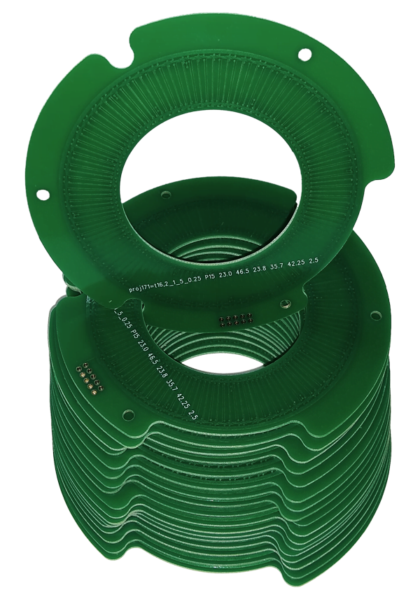
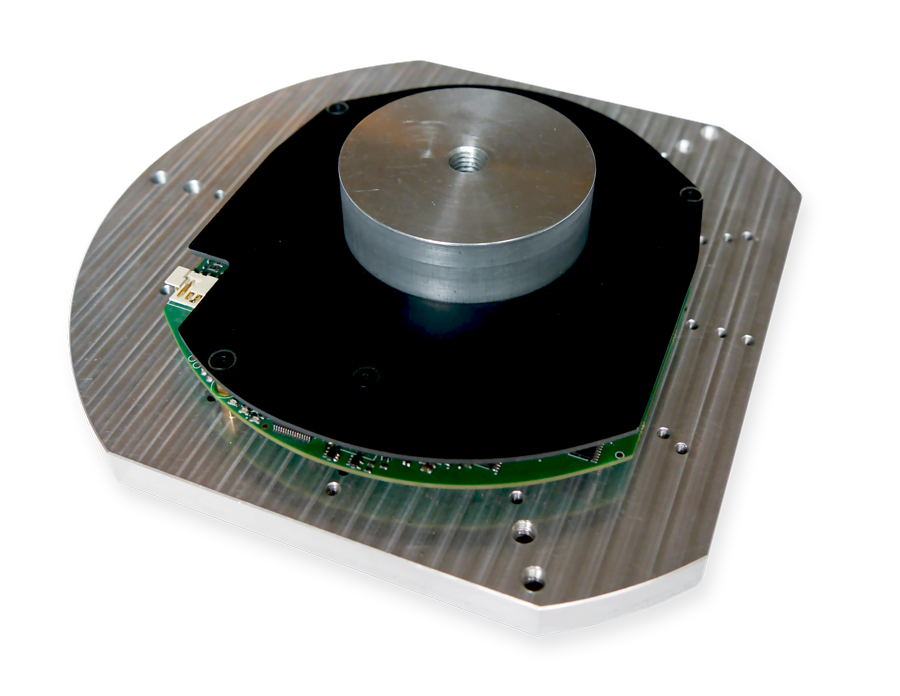
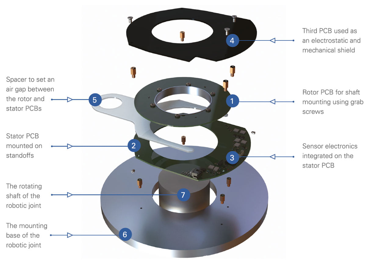
Stator PCBs with excitation and receive coils
A metal target alternates between metal and open areas. The resulting rectangular wave shielding pattern produces receive signals with substantial harmonic content.
We design our resonant target on a PCB, etching eight turns of planar coil from copper via conventional PCB fabrication steps. The multiturn design allows us to shape the target’s electromagnetic field into a close approximation of a sinusoidal pattern, and the receive signals follow. Our inductive encoder produces ratiometric sine and cosine signals with low harmonic distortion.
Accuracy pays for everything else. Because the error inside each fine-scale period is small, we do not need many fine-scale periods.
We run N = 16 where a conventional design needs 64, and we still hold ±9 arcsec at a diameter where comparable inductive encoders publish ±40 or ±80 arcsec position accuracy.
Sixteen periods instead of sixty-four gives four times longer spatial pitch. Inductive coupling range scales with pitch, so the nominal sensing gap and axial margin scale with it, allowing assembly without precision shimming or air-gap inspection.
Fine-scale periods, where a conventional design needs 64
Comparable encoders specify between ±40″ to ±80″.
Longer spatial pitch, and with it the sensing gap
Nominal air gap and axial tolerance, in millimetres
Uncorrected thermal drift of the non-linear error in a metal-target inductive encoder typically exceeds ten times its specified position accuracy. Self-calibration eliminates it on a rotating axis.
Zettlex deserve credit for being the only company publishing a thermal drift coefficient: 1 ppm/K referred to full scale, or roughly 104 arcsec across an 80 °C swing. Their Ultra Kit Encoder range halves these figures to 0.5 ppm/K and 52 arcsec for the same temperature swing.
Zettlex is the only other manufacturer that is using resonant target technology. With direct breakthrough significantly reduced, the remaining drift is analogue receive-chain drift, which can be characterised and specified.
Metal-target suppliers use high N to reduce the angular travel needed for motion-gated self-calibration, which is about fourteen degrees at N = 64. Many axes deliver that travel often enough to keep corrections fresh through the thermal span. This keeps rotation-dependent self-calibration viable across many applications.
The shorter spatial period means a smaller nominal air gap and tighter permitted air-gap variation. You pay for it in installation costs — shimming, inspection, assembly yield and reduced margin for the machine to deflect, wear and run hot without going out of specification.
Fewer fine-scale periods widen our installation margin but increase the angular travel required for motion-gated self-calibration: about 14° at N = 64, 28° at N = 32, 56° at N = 16 and 112° at N = 8.
After initial installation, the axis can make the partial turn required for motion-gated self-calibration. However, gimbals, direct drives holding position, and arms working through small arcs cannot regularly supply 56° of travel. Our patented architecture was developed to self-calibrate the analogue receive chain without relying on rotation.
The prerequisite was a hundredfold reduction in direct breakthrough using a resonant target. In a metal-target sensor, the dominant electrical zero shift depends on sensor geometry, air gap and the excitation circuit’s self-resonant frequency. No firmware algorithm has enough information to correct these sources of electrical zero drift while the rotor is stationary.
The dominant remaining zero shift in resonant target encoders is the electrical offset of our analogue receive chain. Our patented architecture corrects analogue-chain offset and gain at a 400 Hz update rate without rotation, maintaining datasheet accuracy even when angular motion is restricted.
The 400 Hz routine does correct the thermal drift of the small residual direct-breakthrough contribution to electrical zero shift. A separate motion-gated algorithm handles its absolute correction, together with its dependence on installation variation and long-term component ageing, whenever sufficient rotation range is available.
That is the difference between a rotary encoder and an angular encoder. A complete self-calibration architecture and accuracy figures that carry no footnote about rotation.
Start with the required stator outer diameter, clear-bore inner diameter and available supply voltage. Choose from nine standard Kit Encoder sizes, or explore the ruggedised builds in development for 85 mm and 115 mm direct-drive motor frames.


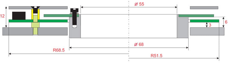

18-bit resolution for 58mm, 19-bit resolution for 25mm through-hole encoders